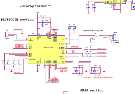
Schematic Capture is a process by which you define your circuits and how everything is connected.
The schematic provides the below necessary definitions:
- Parts definitions
- Part numbers
- Reference designators
- Nets or the lines that show how a part is connected to another part
A schematic can be a single page or several pages that are used to define your project.
The more accurate the schematic is the better, as this will provide the netlist that is used during the PCB layout.
BTI utilizes the latest Cadence®, Mentor Graphics®, and Altium® schematic capture packages for schematic creation and editing.
BTI inserts the necessary data to make the Netlist output port right into the PCB layout software and includes all the necessary information to make this seamless.
Get a Quote Today: Learn More